
TM 5-3805-298-23-2
0180
INSTALLATION CONTINUED
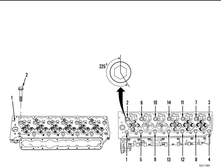
9. Lubricate 14 new cylinder head bolts (Figure 14, Item 2) with clean engine oil and install on cylinder head
(Figure 14, Item 1).
10. Tighten cylinder head bolts (Figure 14, Item 2) in sequence shown to 37 lb-ft (50 Nm).
11. Tighten cylinder head bolts (Figure 14, Item 2) in sequence shown to 74 lb-ft (100 Nm).
12. Tighten cylinder head bolts (Figure 14, Item 2) in sequence shown an additional 225 degrees.
Figure 14. Cylinder Head Bolt Tightening Sequence.
0180