
TM 5-3805-298-23-2
0200
FUEL PRIME PUMP AND BASE INSTALLATION CONTINUED
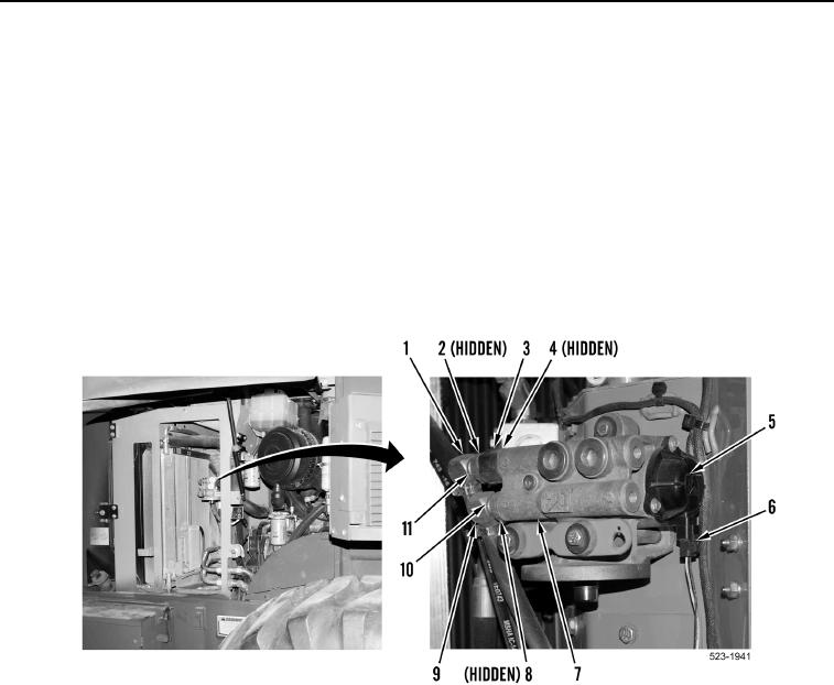
4. Connect rear frame wiring harness connector (Figure 9, Item 6) and fuel prime pump (Figure 9, Item 5).
NOTE
Remove caps or plugs from fittings and ports and install fittings as noted during removal.
5. Install new O-ring (Figure 9, Item 8), elbow fitting (Figure 9, Item 9) and jam nut (Figure 9, Item 10) on fuel
prime pump and base (Figure 9, Item 7).
6. Install new O-ring (Figure 9, Item 4) and adapter (Figure 9, Item 3) on fuel prime pump base
(Figure 9, Item 7).
7. Install new O-ring (Figure 9, Item 2,) elbow fitting (Figure 9, Item 1) and jam nut (Figure 9, Item 11) on adapter
(Figure 9, Item 3).
Figure 9. Elbow Fittings and Adapter at Fuel Prime Pump and Base.
0200