
TM 5-3805-298-23-2
0203
INSTALLATION CONTINUED
NOTE
Fuel injection pump must remain locked until procedure instructs to unlock.
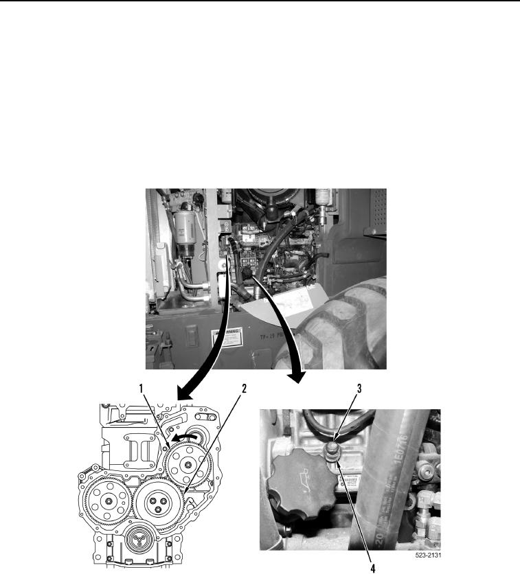
28. Loosen lock bolt (Figure 26, Item 3) and slide lockwasher (Figure 26, Item 4) over to small hole blocking lock
bolt from full engagement.
29. Tighten lock bolt (Figure 26, Item 3) to 80 lb-in. (9 Nm).
30. Apply pressure to fuel injection pump gear (Figure 26, Item 1) in a counterclockwise direction.
31. Verify marked position of three gears (Figure 26, Item 2).
Figure 26. Fuel Injection Pump Lock.
0203