
TM 5-3805-298-23-2
0203
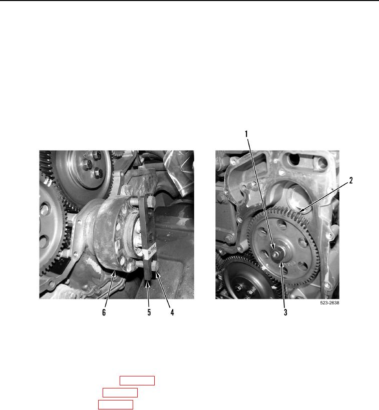
INSTALLATION CONTINUED
NOTE
Ensure timing marks on gears are in alignment and mesh of gears are correct.
38. With assistance, using a 1/2 drive ratchet and crankshaft turning tool (Figure 30, Item 5) do not allow engine to
turn and tighten nut (Figure 30, Item 3) on fuel injection pump shaft (Figure 30, Item 1) to 66 lb-ft (90 Nm).
39. Insure timing marks on gears (Figure 30, Item 2) are in alignment.
40. Remove two bolts (Figure 30, Item 4) and crankshaft turning tool (Figure 30, Item 5) from hub
(Figure 30, Item 6).
Figure 30. Fuel Injection Pump Gear.
0203
END OF TASK
FOLLOW-ON TASKS
000203
1. Install crankcase breather base (WP 0189).
2. Install secondary fuel filter (WP 0220).
3. Install engine front cover (WP 0188).
4. Verify correct operation of machine (TM 5-3805-298-10).
END OF TASK
END OF WORK PACKAGE
0203-27/(28 blank)