
TM 5-3805-298-23-2
0203
INSTALLATION CONTINUED
35. Remove crankshaft timing pin (Figure 28, Item 1) and crankshaft timing pin adapter (Figure 28, Item 2) from
engine.
Figure 28. Crankshaft Timing Pin.
0203
NOTE
Remove caps or plugs from hoses, tubes, and open ports.
Install hoses and tube as noted during removal.
Route hose and tube as noted during removal.
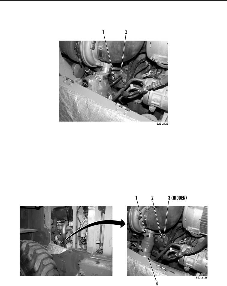
36. Install new O-ring (Figure 29, Item 3) and plug (Figure 29, Item 2) on engine.
37. Install hose and tube (Figure 29, Item 4) and clamp (Figure 29, Item 1) on machine.
Figure 29. Aftercooler Pipe.
0203