
TM 5-3805-298-23-4
0376
REMOVAL CONTINUED
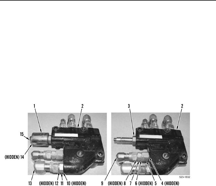
7. Remove nut (Figure 3, Item 15), washer (Figure 3, Item 14), solenoid (Figure 3, Item 1), and cartridge
(Figure 3, Item 3) from ride control valve (Figure 3, Item 2).
NOTE
Note position and orientation of fittings to aid installation.
8. Remove four elbow fittings (Figure 3, Item 13) and O-rings (Figure 3, Item 12) from adapters (Figure 3,
Item 11). Discard O-rings.
9. Remove four adapters (Figure 3, Item 11) and O-rings (Figure 3, Item 10) from ride control valve (Figure 3,
Item 2). Discard O-rings.
10. Remove elbow fitting (Figure 3, Item 9), O-ring (Figure 3, Item 8), check valve (Figure 3, Item 7), and
O-ring (Figure 3, Item 6) from adapter (Figure 3, Item 5). Discard O-rings.
11. Remove adapter (Figure 3, Item 5) and O-ring (Figure 3, Item 4) from ride control valve (Figure 3, Item 2).
Discard O-ring.
Figure 3. Ride Control Valve and Fittings.
0376
END OF TASK
CLEANING AND INSPECTION
000376
Clean and inspect all parts IAW Mechanical General Maintenance Instructions (WP 0172).
END OF TASK