
TM 5-3805-298-23-4
0378
REMOVAL CONTINUED
CAUTION
Cap or plug fittings and open ports on differential lock valve to protect against
contamination. Failure to follow this caution may result in damage to equipment.
NOTE
Note orientation and position of fittings to aid installation.
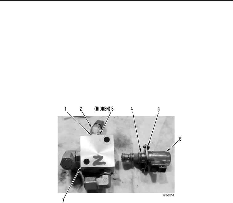
6. Loosen three jam nuts (Figure 4, Item 1), and remove three elbow fittings (Figure 4, Item 2) and O-rings
(Figure 4, Item 3) from differential lock valve (Figure 4, Item 7). Discard O-rings.
7. Remove two bolts (Figure 4, Item 5) and differential lock solenoid (Figure 4, Item 6) from differential lock valve
(Figure 4, Item 7).
8. Remove three O-rings (Figure 4, Item 4) from differential lock solenoid (Figure 4, Item 6). Discard O-rings.
Figure 4. Differential Lock Solenoid.
0378
END OF TASK
CLEANING AND INSPECTION
000378
Clean and inspect all parts IAW Mechanical General Maintenance Instructions (WP 0172).
Clean and inspect all parts IAW Electrical General Maintenance Instructions (WP 0174).
END OF TASK