
14
TM 5-3805-298-23-4
FIELD MAINTENANCE
-
PILOT VALVE ASSEMBLY REPLACEMENT
037
9
Removal, Cleaning and Inspection, Installation
INITIAL SETUP
Materials/Parts - Continued
Tools and Special Tools
0
0
Tool Kit, General Mechanic's
O-ring, 3J-1907 (WP 0432, Item 109) (8)
0
(WP 0431, Item 162)
O-ring, 6V-8397 (WP 0432, Item 140) (7)
0
0
Socket Driver, Torx, 3/8" Drive, T-30
O-ring, 6V-8398 (WP 0432, Item 141)
0
(WP 0431, Item 125)
0
References
Tool, Wedge Removal
0
WP 0172
(WP 0431, Item 164)
0
0
WP 0174
0
Materials/Parts
0
Equipment Conditions
Cap Set, Protective (WP 0430, Item 4)
0
0
Rag, Wiping (WP 0430, Item 27)
Machine parked (TM 5-3805-298-10)
0
0
Tag, Marker (WP 0430, Item 35)
Hydraulic tank drained (WP 0368)
0
0
Tiedown Strap, Electrical Components
Estimated Time to Complete
0
(WP 0430, Item 40)
0
3.5 Hr
0
REMOVAL
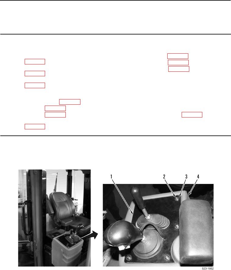
000379
1. Remove six bolts (Figure 1, Item 2), washers (Figure 1, Item 3) and plate (Figure 1, Item 1) from operator
console (Figure 1, Item 4).
Figure 1. Pilot Valve Cover.
0379