
TM 5-3805-298-23-4
0378
REMOVAL CONTINUED
NOTE
Tag and mark wiring harness connector to aid installation.
Note wiring harness routing to aid installation.
Note position and location of tiedown straps to aid installation.
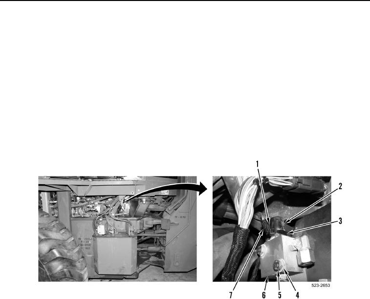
3. Remove tiedown strap (Figure 3, Item 3) from differential lock solenoid (Figure 3, Item 2) and front frame wiring
harness (Figure 3, Item 7). Discard tiedown strap.
4. Disconnect front frame wiring harness connector (Figure 3, Item 1) from differential lock solenoid (Figure 3,
Item 2).
5. Remove two bolts (Figure 3, Item 5), washers (Figure 3, Item 4), and differential lock valve (Figure 3, Item 6)
from machine.
Figure 3. Front Frame Harness Connector.
0378