• Home
  • Download PDF
  • Order CD-ROM
  • Order in Print
Figure 7. Right Side Hydraulic Tank Hoses.
Figure 9. Hydraulic Tank.

Field Maintenance Manual For 924H Wheel Loader -4 Page Navigation
  298    299    300    301    302  303  304    305    306    307    308  
img
.
TM 5-3805-298-23-4
0392
REMOVAL CONTINUED
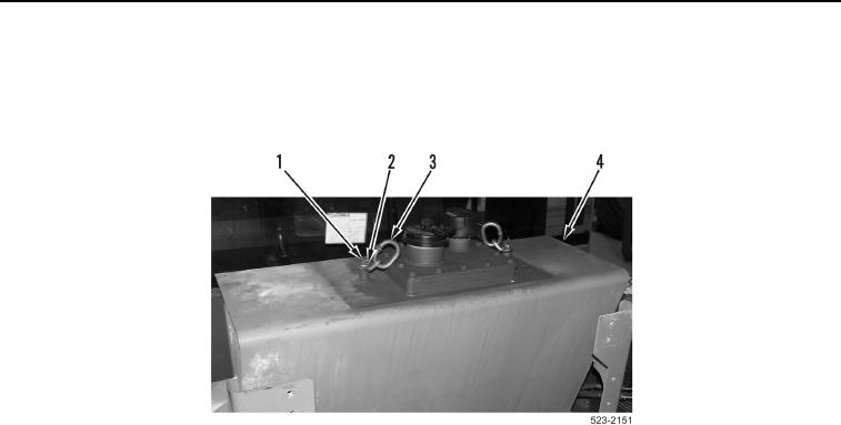
15. Remove two bolts (Figure 8, Item 1), washers (Figure 8, Item 2) from hydraulic tank (Figure 8, Item 4).
16. Install two bracket links (Figure 8, Item 3), washers (Figure 8, Item 2), and bolts (Figure 8, Item 1) on hydraulic
tank (Figure 8, Item 4).
Figure 8. Lifting Links.
0392
0392-9


Privacy Statement
Press Release
Contact

© Copyright Integrated Publishing, Inc.. All Rights Reserved.