
TM 5-3805-298-23-4
0392
DISASSEMBLY CONTINUED
NOTE
Note position and orientation of fittings to aid installation.
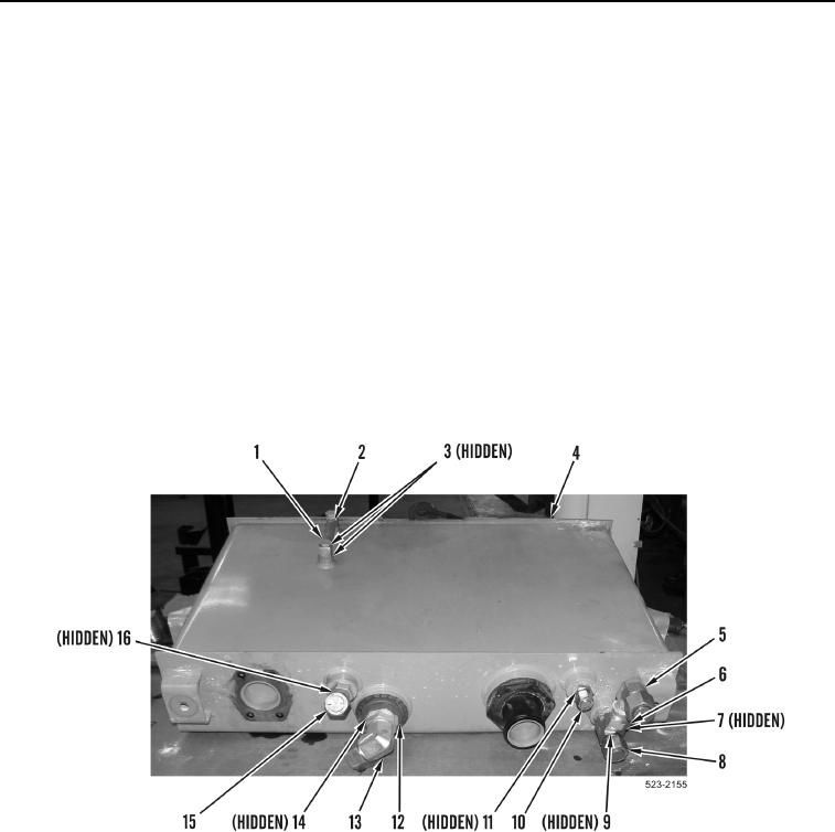
5. Remove fitting (Figure 12, Item 15) and O-ring (Figure 12, Item 16) from hydraulic tank (Figure 12, Item 4).
Discard O-ring.
6. Remove fitting (Figure 12, Item 13) and O-ring (Figure 12, Item 14) from hydraulic tank screen
(Figure 12, Item 12). Discard O-ring.
7. Remove fitting (Figure 12, Item 10) and O-ring (Figure 12, Item 11) from hydraulic tank (Figure 12, Item 4).
Discard O-ring.
8. Loosen tube nut (Figure 12, Item 6) and remove fitting (Figure 12, Item 5) and O-ring (Figure 12, Item 7) from
hydraulic tank (Figure 12, Item 4). Discard O-ring.
9. Remove fitting (Figure 12, Item 8) and O-ring (Figure 12, Item 9) from hydraulic tank (Figure 12, Item 4).
Discard O-ring.
10. Remove two bolts (Figure 12, Item 1), O-rings (Figure 12, Item 3), and gauge (Figure 12, Item 2) from hydraulic
tank (Figure 12, Item 4). Discard O-rings.
Figure 12. Hydraulic Tank Fittings.
0392