
TM 5-3805-298-23-4
0392
INSTALLATION CONTINUED
NOTE
Install electrical connectors and route wiring harness as noted during removal.
Install tiedown straps as noted during removal.
Install spacers as noted during removal.
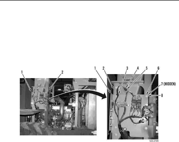
17. Install panel (Figure 24, Item 1), spacers (Figure 24, Item 7), ladder clip (Figure 24, Item 3), four washers
(Figure 24, Item 8), and bolts (Figure 24, Item 6) on hydraulic tank frame (Figure 24, Item 2).
18. Connect engine wiring harness connector (Figure 24, Item 4) on hydraulic temperature sensor
(Figure 24, Item 5).
Figure 24. Panel.
0392