
TM 5-3805-298-23-4
0392
INSTALLATION
000392
WARNING
Use extreme caution when handling heavy parts. Provide adequate support and use
assistance during procedure. Failure to follow this warning may result in injury or death to
personnel.
NOTE
Hydraulic tank weighs approximately 170 lb (77 kg).
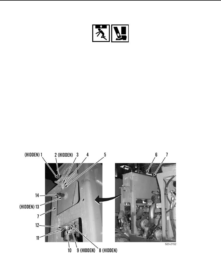
1. Install lifting device on two bracket links (Figure 17, Item 6).
2. Using lifting device install hydraulic tank (Figure 17, Item 7) on machine.
3. Remove lifting device from two bracket links (Figure 17, Item 6).
4. Install two washers (Figure 17, Item 2), bolts (Figure 17, Item 1), large washers (Figure 17, Item 3), washers
(Figure 17, Item 4) and nuts (Figure 17, Item 5) on hydraulic tank (Figure 17, Item 7).
5. Install two large washers (Figure 17, Item 12), washers (Figure 17, Item 11), bolts (Figure 17, Item 10),
washers (Figure 17, Item 9) and nuts (Figure 17, Item 8) on hydraulic tank (Figure 17, Item 7).
6. Install new O-ring (Figure 17, Item 13) and hydraulic temperature sensor (Figure 17, Item 14) on hydraulic tank
(Figure 17, Item 7).
Figure 17. Hydraulic Tank.
0392