
TM 5-3805-298-23-4
0392
INSTALLATION CONTINUED
NOTE
Install hoses and wiring harness connectors as noted during removal.
Remove caps from hoses and fittings prior to installation.
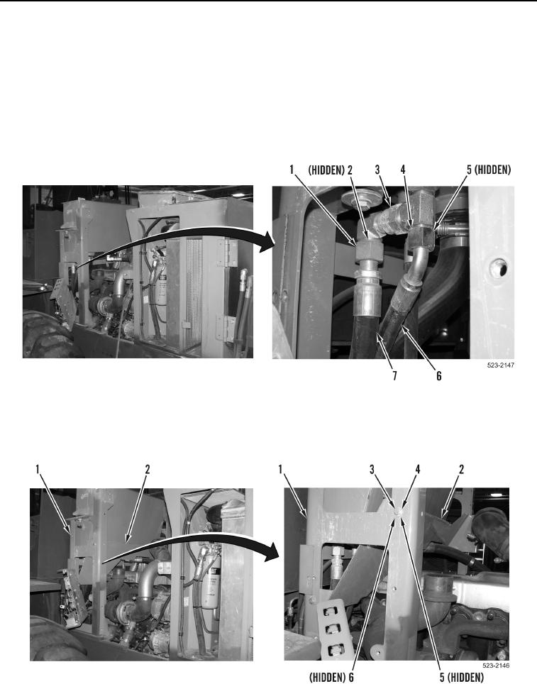
14. Install new O-ring (Figure 22, Item 2), hose (Figure 22, Item 7), and tube nut (Figure 22, Item 1) on fitting
(Figure 22, Item 3).
15. Install new O-ring (Figure 22, Item 5), hose (Figure 22, Item 6), and tube nut (Figure 22, Item 4) on fitting
(Figure 22, Item 3).
Figure 22. Left Side Hydraulic Tank Hoses.
0392
16. Install panel (Figure 23, Item 2), two washers (Figure 23, Item 4), washers (Figure 23, Item 6), nuts
(Figure 23, Item 5) and bolts (Figure 23, Item 3) on hydraulic tank frame (Figure 23, Item 1).
Figure 23. Panel.
0392