
TM 5-3805-298-23-4
0392
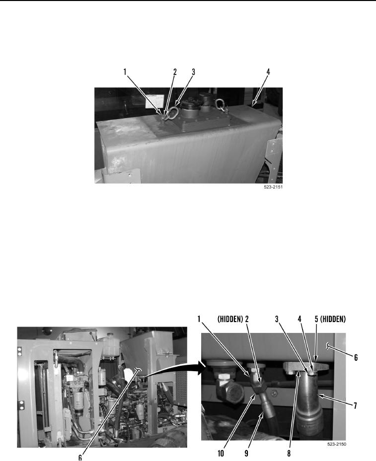
INSTALLATION CONTINUED
7. Remove two bolts (Figure 18, Item 1), washers (Figure 18, Item 2) and bracket links (Figure 18, Item 3) from
hydraulic tank (Figure 18, Item 4).
8. Install two washers (Figure 18, Item 2) and bolts (Figure 18, Item 1) on hydraulic tank (Figure 18, Item 4).
Figure 18. Lifting Links.
0392
NOTE
Install hoses and wiring harness connectors as noted during removal.
Remove caps from hoses and fittings prior to installation.
9. Install new O-ring (Figure 19, Item 5), hose (Figure 19, Item 7), two split flange clamps (Figure 19, Item 8), four
washers (Figure 19, Item 4) and bolts (Figure 19, Item 3) on hydraulic tank (Figure 19, Item 6).
10. Install new O-ring (Figure 19, Item 2), hose (Figure 19, Item 9) and tube nut (Figure 19, Item 10) on fitting
(Figure 19, Item 1).
Figure 19. Right Side Hydraulic Tank Hoses.
0392