
TM 5-3805-298-23-4
0392
INSTALLATION CONTINUED
NOTE
Install hoses and wiring harness connectors as noted during removal.
Remove caps from hoses and fittings prior to installation.
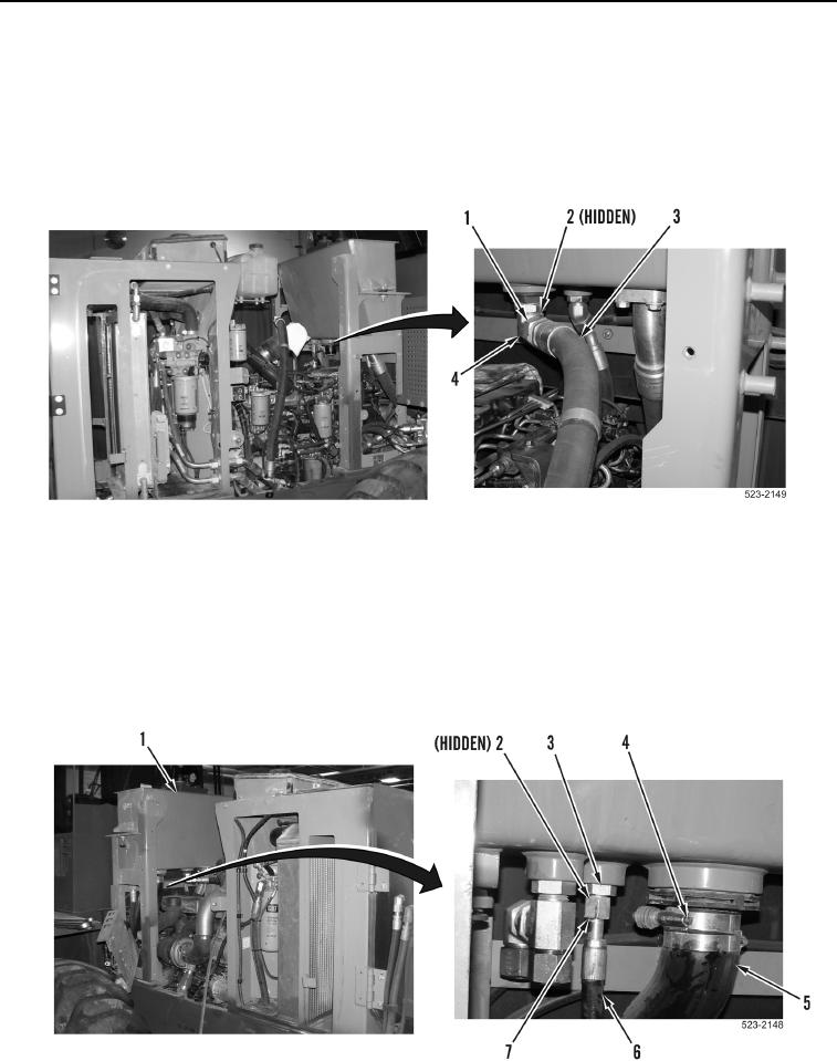
11. Install new O-ring (Figure 20, Item 2), hose (Figure 20, Item 3) and tube nut (Figure 20, Item 1) on fitting
(Figure 20, Item 4).
Figure 20. Gear Pump Supply Hoses.
0392
NOTE
Install hoses and wiring harness connectors as noted during removal.
Remove caps from hoses and fittings prior to installation.
12. Install hose (Figure 21, Item 5) and two clamps (Figure 21, Item 4) on hydraulic tank (Figure 21, Item 1).
13. Install new O-ring (Figure 21, Item 2), hose (Figure 21, Item 6) and tube nut (Figure 21, Item 7) on fitting
(Figure 21, Item 3).
Figure 21. Hydraulic Tank Supply Hoses.
0392