
TM 5-3805-298-23-4
0392
INSTALLATION CONTINUED
NOTE
Install electrical connectors and route wiring harness as noted during removal.
Install tiedown straps as noted during removal.
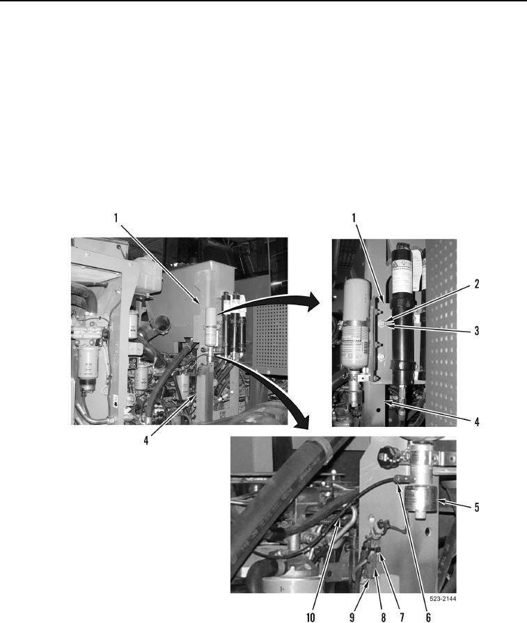
19. Install accumulator panel (Figure 25, Item 1), four washers (Figure 25, Item 3), and bolts (Figure 25, Item 2) on
hydraulic tank frame (Figure 25, Item 4).
20. Install ether line (Figure 25, Item 10) and tube nut (Figure 25, Item 6) on ether valve (Figure 25, Item 5).
21. Connect rear frame wiring harness connector (Figure 25, Item 8) on ether aid solenoid connector
(Figure 25, Item 9).
22. Install new tiedown strap (Figure 25, Item 7) on rear frame wiring harness connector (Figure 25, Item 8).
Figure 25. Accumulator Panel.
0392
END OF TASK