
TM 5-2420-231-23-2
0111
REMOVAL CONTINUED
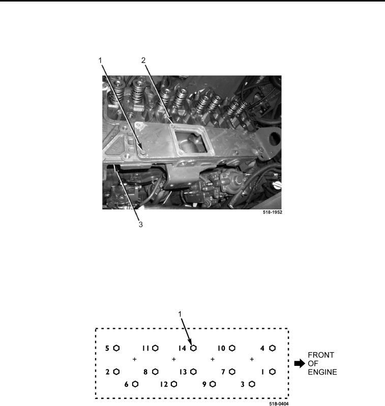
21. Remove four bolts (Figure 10, Item 1) and intake cover plate (Figure 10, Item 2) from cylinder head
(Figure 10, Item 3).
Figure 10. Intake Cover Plate.
0111
CAUTION
Follow cylinder head bolt loosening sequence to prevent cylinder head distortion.
22. Gradually and evenly loosen 14 cylinder head bolts (Figure 11, Item 1) in sequence shown.
Figure 11. Cylinder Head Bolt Loosening Sequence.
0111