
TM 5-2420-231-23-2
0111
DISASSEMBLY
0111
NOTE
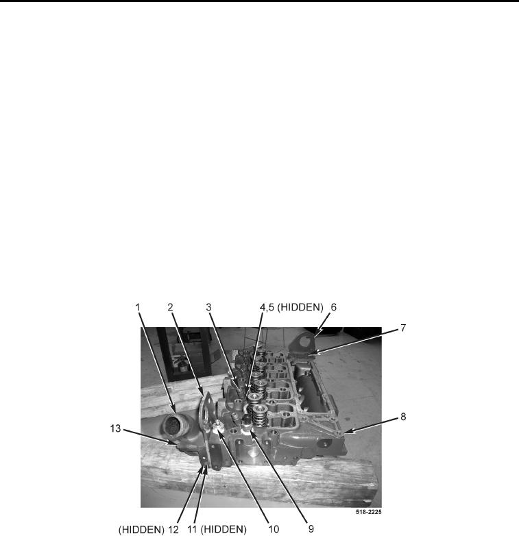
Note length and position of each thermostat bolt to aid in assembly.
1. Remove three bolts (Figure 13, Item 13), thermostat housing (Figure 13, Item 1), lifting bracket (Figure 13,
Item 2), gasket (Figure 13, Item 12), and thermostat (Figure 13, Item 11) from cylinder head (Figure 13,
Item 8). Discard gasket.
2. Remove two bolts (Figure 13, Item 7) and rear lifting bracket (Figure 13, Item 6) from cylinder head
(Figure 13, Item 7).
3. Remove coolant temperature sensor (Figure 13, Item 9) from cylinder head (Figure 13, Item 8).
4. Remove coolant temperature switch (Figure 13, Item 10) from cylinder head (Figure 13, Item 8).
5. Remove four fuel injector collars (Figure 13, Item 4) and O-rings (Figure 13, Item 5) from fuel injectors
(Figure 13, Item 3). Discard O-rings.
NOTE
Note position and orientation of fuel injectors to aid in assembly.
6. Using injector puller, remove four fuel injectors (Figure 13, Item 3) from cylinder head (Figure 13, Item 8).
Figure 13. Cylinder Head Components.
0111