
TM 5-2420-231-23-2
0111
DISASSEMBLY CONTINUED
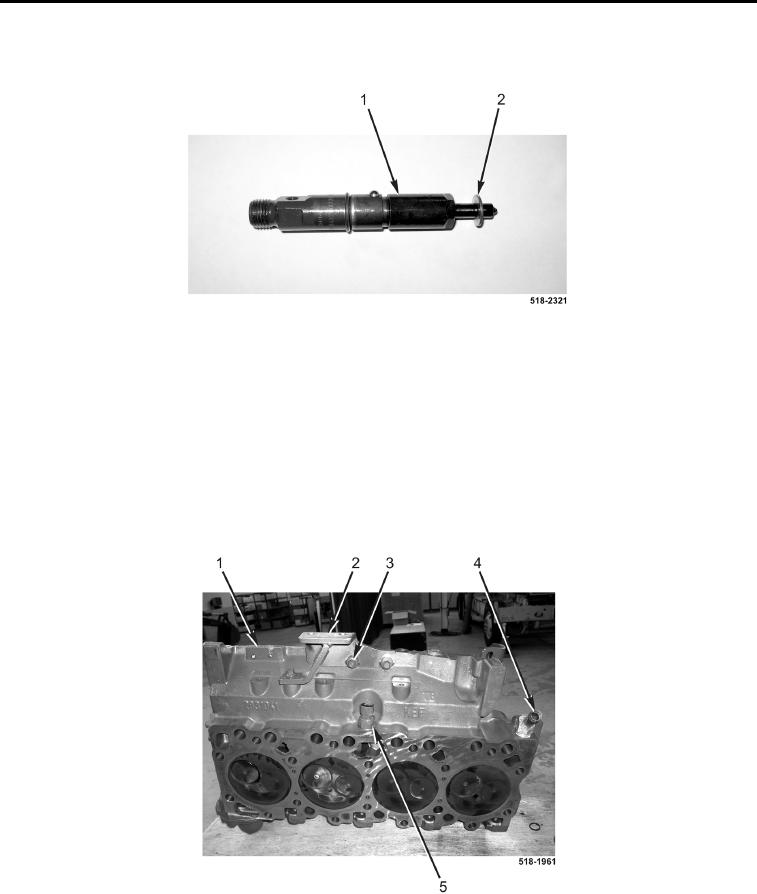
7. Remove four crushwashers (Figure 14, Item 2) from fuel injectors (Figure 14, Item 1). Discard crushwashers.
Figure 14. Fuel Injector Crushwashers.
0111
8. Remove three bolts (Figure 15, Item 3) and fuel filter bracket (Figure 15, Item 2) from cylinder head
(Figure 15, Item 1).
NOTE
Note orientation of coolant fitting to aid in assembly.
9. Remove coolant fitting (Figure 15, Item 4) from cylinder head (Figure 15, Item 1).
10. Remove cold start temperature switch (Figure 15, Item 5) from cylinder head (Figure 15, Item 1).
Figure 15. Filter Bracket.
0111
END OF TASK