
TM 5-2420-231-23-2
0160
REMOVAL CONTINUED
NOTE
Mounting bolts, lockwashers, and spacer are held in place by O-rings.
4. Loosen three mounting bolts (Figure 4, Item 3) and position mounting plate (Figure 4, Item 2) away from bulk-
head (Figure 4, Item 1).
5. Remove three O-rings (Figure 4, Item 6), spacers (Figure 4, Item 5), lockwashers (Figure 4, Item 4), bolts
(Figure 4, Item 3), and one clamp (Figure 4, Item 7) from mounting plate (Figure 4, Item 2). Discard O-rings
and lockwashers.
Figure 4. Mounting Bolts.
0160
NOTE
Tag and mark wires to aid in installation.
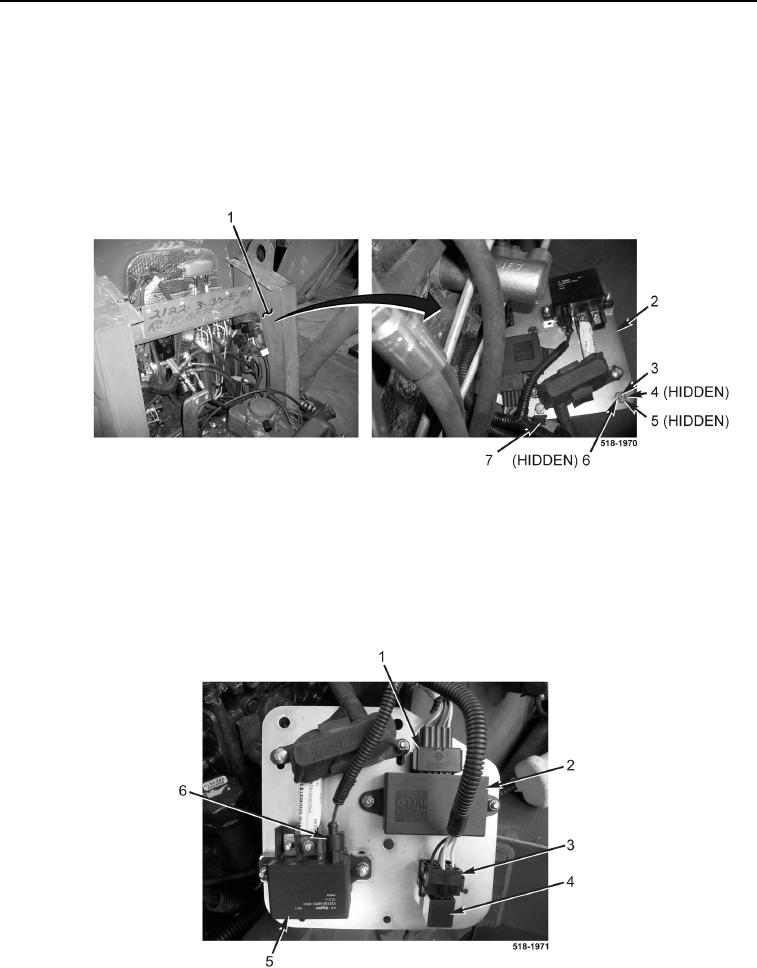
6. Disconnect wiring harness connector (Figure 5, Item 1) from grid heater module (Figure 5, Item 2).
7. Disconnect wiring harness connector (Figure 5, Item 6) from grid heater relay (Figure 5, Item 5).
8. Remove relay (Figure 5, Item 4) from relay mount (Figure 5, Item 3).
Figure 5. Controller Connector.
0160