TM 5-2420-231-23-2
0160
REMOVAL CONTINUED
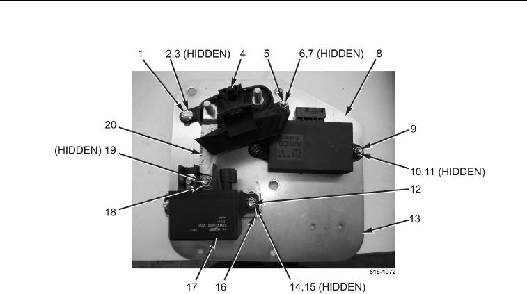
Figure 7. Bus Bar.
0160
END OF TASK
CLEANING AND INSPECTION
0160
1. Clean and inspect all parts IAW Mechanical General Maintenance Instructions (WP 0369).
2. Clean and inspect all parts IAW Electrical General Maintenance Instructions (WP 0370).
END OF TASK
INSTALLATION
0160
1. Loosely install fuse block (Figure 7, Item 4), bolt (Figure 7, Item 1), washer (Figure 7, Item 3), and new locknut
(Figure 7, Item 2) on mounting plate (Figure 7, Item 13).
2. Loosely install two washers (Figure 7, Item 6), bolt (Figure 7, Item 7), and new locknut (Figure 7, Item 5) on
fuse block (Figure 7, Item 4).
3. Loosely install spacer (Figure 7, Item 16), relay (Figure 7, Item 17), four washers (Figure 7, Item 14), two bolts
(Figure 7, Item 15), and new locknuts (Figure 7, Item 12) on mounting plate (Figure 7, Item 13).
4. Install bus bar (Figure 7, Item 20), washer (Figure 7, Item 19), and nut (Figure 7, Item 18) on fuse block
(Figure 7, Item 4) and relay (Figure 7, Item 17).
5. Tighten bolt (Figure 7, Item 1), bolt (Figure 7, Item 7), and bolts (Figure 7, Items 15).
6. Install controller (Figure 7, Item 8), four washers (Figure 7, Item 10), two bolts (Figure 7, Item 11), and new
locknuts (Figure 7, Item 9) on mounting plate (Figure 7, Item 13).

