
TM 5-2420-231-23-2
0160
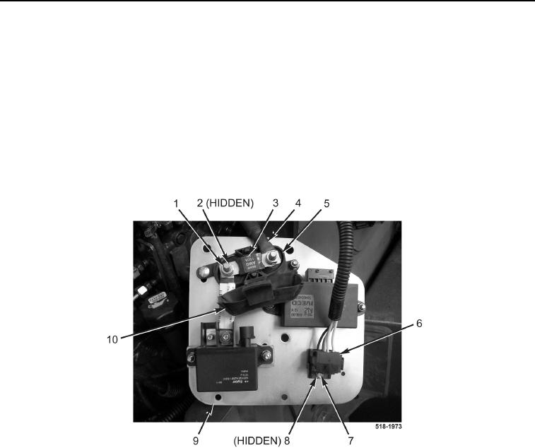
INSTALLATION CONTINUED
7. Position mounting plate (Figure 8, Item 9) on machine.
NOTE
Install wires as tagged and marked during removal.
8. Install cable (Figure 8, Item 4), fuse (Figure 8, Item 3), two new lockwashers (Figure 8, Item 2), and nuts
(Figure 8, Item 1) on fuse block (Figure 8, Item 5).
9. Position cover (Figure 8, Item 10) on fuse block (Figure 8, Item 5).
10. Install relay mount (Figure 8, Item 6), bolt (Figure 8, Item 7), and new locknut (Figure 8, Item 8) on mounting
plate (Figure 8, Item 9).
Figure 8. Relay Mount.
0160
NOTE
Install wires as tagged and marked during removal.
11. Install relay (Figure 9, Item 4) on relay mount (Figure 9, Item 3).
12. Connect wiring harness connector (Figure 9, Item 6) to grid heater relay (Figure 9, Item 5).
13. Connect wiring harness connector (Figure 9, Item 1) to grid heater module (Figure 9, Item 2).