
10
TM 5-2420-231-23-2
FIELD MAINTENANCE
-
FRONT CONSOLE WIRING HARNESS REPLACEMENT
0162
Removal, Cleaning and Inspection, Installation
INITIAL SETUP
References - Continued
Tools and Special Tools
Tool Kit, General Mechanic's
WP 0370
0
0
(WP 0376, Item 117)
WP 0374 (Group Number 0306)
0
Materials/Parts
Equipment Conditions
Rag, Wiping (WP 0375, Item 25)
Instrument panel front covers removed
0
0
Tiedown Strap (WP 0375, Item 35)
0
Locknut (10)
Estimated Time to Complete
0
References
3.2 hr
0
WP 0369
0
REMOVAL
0162
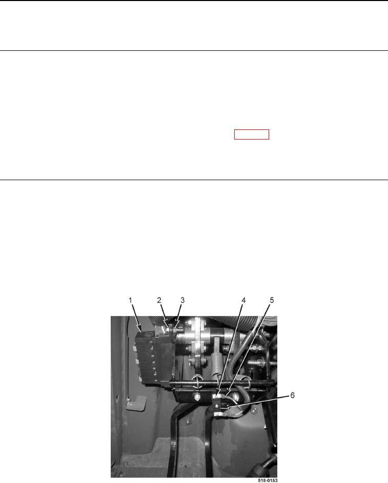
1. Remove bolt (Figure 1, Item 2), locknut (Figure 1, Item 3), and fuse block (Figure 1, Item 1) from machine.
Position fuse block aside. Discard locknut.
NOTE
Tag and mark wires to aid in installation.
2. Remove two screws (Figure 1, Item 4) and disconnect two front console wiring harness connectors (Figure 1,
Item 5) from brake switch (Figure 1, Item 6).
Figure 1. Fuse Block.
0162