
TM 5-2420-231-23-2
0167
INSTALLATION CONTINUED
5. Connect powershift wiring harness connector (Figure 4, Item 2) to left brake pressure sensor connector
(Figure 4, Item 1).
Figure 4. Left Brake Pressure Sensor Connector.
0167
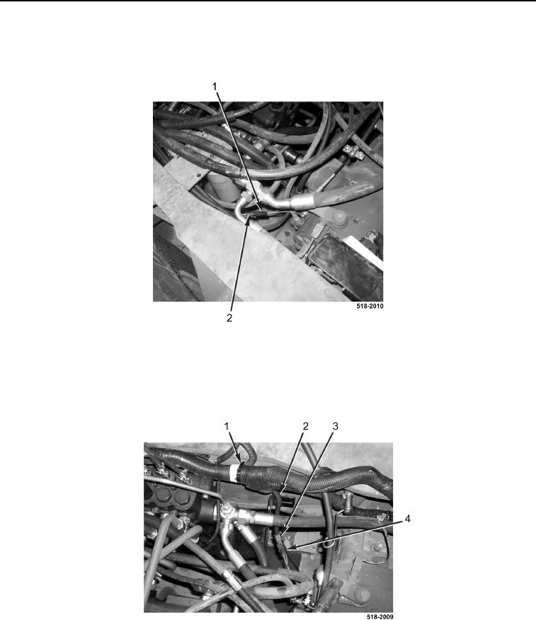
6. Connect powershift wiring harness connector (Figure 5, Item 3) to right brake pressure sensor connector
(Figure 5, Item 4).
7. Install new tiedown strap (Figure 5, Item 1) on powershift wiring harness (Figure 5, Item 2).
Figure 5. Right Brake Pressure Sensor Connector.
0167
END OF TASK