
6
TM 5-2420-231-23-2
FIELD MAINTENANCE
-
POWERSHIFT WIRING HARNESS REPLACEMENT
0167
Removal, Cleaning and Inspection, Installation
INITIAL SETUP
References - Continued
Tools and Special Tools
Tool Kit, General Mechanic's
WP 0370
0
0
(WP 0376, Item 117)
WP 0374 (Group Number 0308)
0
Materials/Parts
Equipment Conditions
Rag, Wiping (WP 0375, Item 25)
Cab assembly removed (WP 0327)
0
0
Tag, Marker (WP 0375, Item 33)
0
Estimated Time to Complete
Tiedown Strap (WP 0375, Item 35)
0
19.0 hr
0
References
WP 0369
0
REMOVAL
0167
NOTE
Tag and mark wires to aid in installation.
Note location and quantity of tiedown straps to aid in installation.
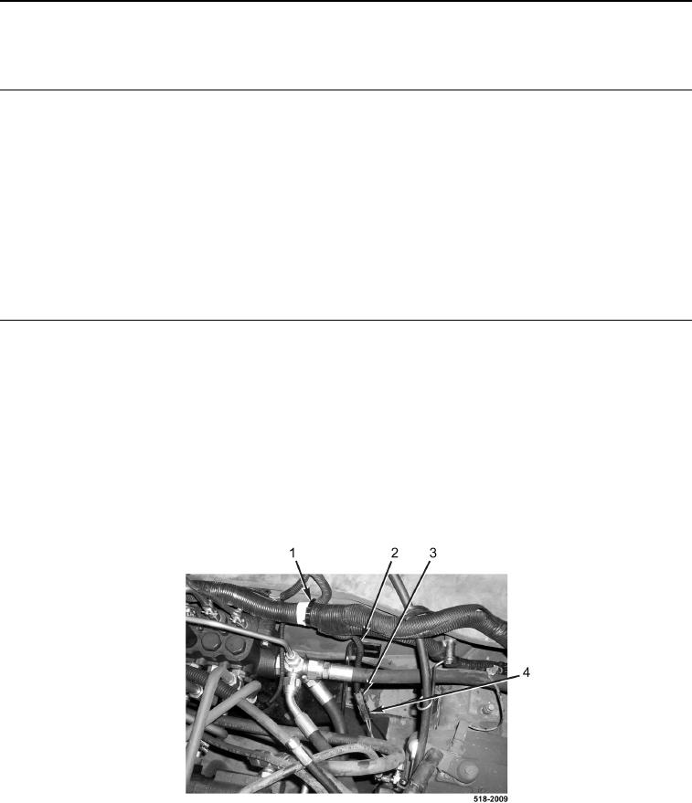
1. Remove tiedown strap (Figure 1, Item 1) from powershift wiring harness (Figure 1, Item 2). Discard tiedown
straps.
2. Disconnect powershift wiring harness connector (Figure 1, Item 3) from right brake pressure sensor connector
(Figure 1, Item 4).
Figure 1. Right Brake Pressure Sensor Connector.
0167