
TM 5-2420-231-23-2
0167
REMOVAL CONTINUED
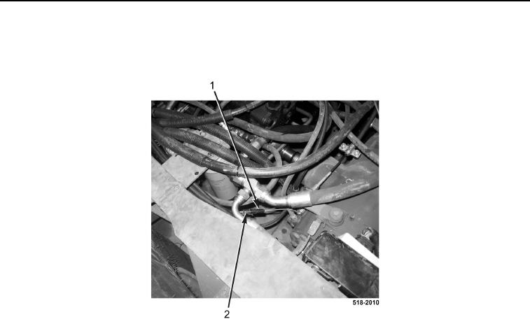
3. Disconnect powershift wiring harness connector (Figure 2, Item 2) from left brake pressure sensor connector
(Figure 2, Item 1).
Figure 2. Left Brake Pressure Sensor Connector.
0167
4. Remove three tiedown straps (Figure 3, Item 1) from powershift wiring harness (Figure 3, Item 4). Discard tie-
down straps.
5. Disconnect 4WD jumper harness (Figure 3, Item 3) from powershift wiring harness connector
(Figure 3, Item 2).
6. Disconnect powershift wiring harness connector (Figure 3, Item 5) from transmission (Figure 3, Item 6).
NOTE
Note routing and location of powershift wiring harness to aid in installation.
7. Remove powershift wiring harness (Figure 3, Item 4) from machine.