
TM 5-2420-231-23-2
0226
ASSEMBLY CONTINUED
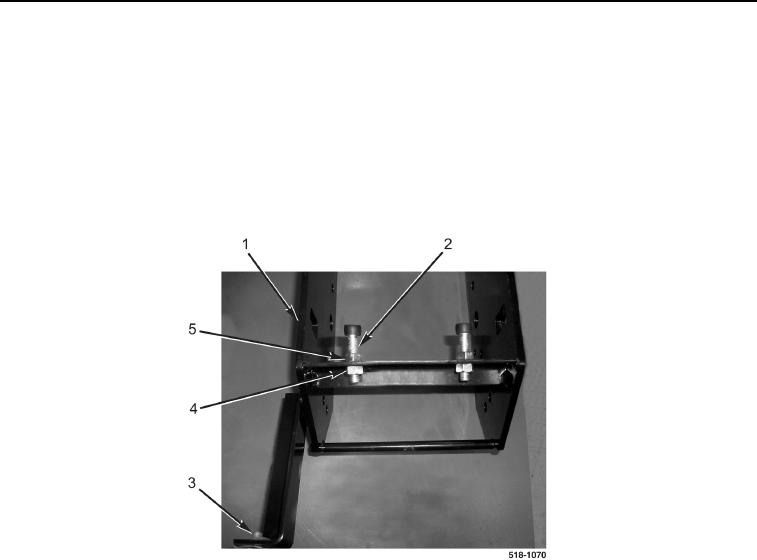
10. Install clip (Figure 15, Item 3) on brake pedal bracket (Figure 15, Item 1).
11. Install two nuts (Figure 15, Item 5) on brake pedal stops (Figure 15, Item 2).
NOTE
Install pedal stops as noted during removal.
12. Install two brake pedal stops (Figure 15, Item 2) and nuts (Figure 15, Item 4) on brake pedal bracket
(Figure 15, Item 1).
Figure 15. Pedal Stops.
0226