
TM 5-2420-231-23-2
0226
ASSEMBLY CONTINUED
NOTE
The procedure for brake pedal disassembly and assembly is identical for left-hand and
right-hand brake pedals. Left-hand brake pedal is shown in this procedure.
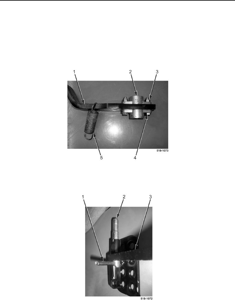
5. Loosely install brake pedal bushing (Figure 13, Item 2), two bolts (Figure 13, Item 4), and new locknuts
(Figure 13, Item 3) on brake pedal (Figure 13, Item 1). Do not tighten.
6. Connect return spring (Figure 13, Item 5) to brake pedal (Figure 13, Item 1).
7. Repeat steps 5 and 6 on right brake pedal.
Figure 13. Brake Pedal.
0226
8. Install brake pedal lock (Figure 14, Item 2) on left brake pedal (Figure 14, Item 3).
9. Install spring pin (Figure 14, Item 1) on brake pedal lock (Figure 14, Item 2).
Figure 14. Brake Pedal Lock.
0226