
TM 5-2420-231-23-3
0263
INSTALLATION CONTINUED
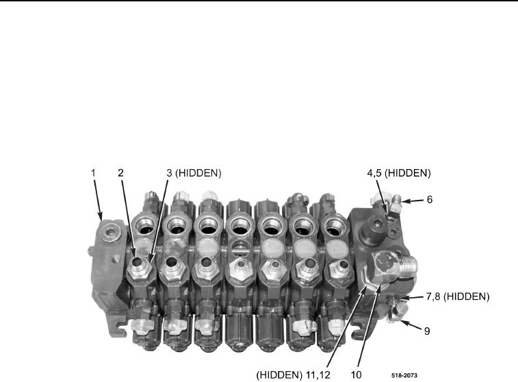
4. Install new O-ring (Figure 10, Item 8) and tee fitting (Figure 10, Item 9), and tighten nut (Figure 10, Item 7) on
backhoe control valve (Figure 10, Item 1).
5. Install new O-ring (Figure 10, Item 12) and elbow fitting (Figure 10, Item 10), and tighten nut (Figure 10,
Item 11) on backhoe control valve (Figure 10, Item 1).
6. Install new O-ring (Figure 10, Item 5) and elbow fitting (Figure 10, Item 6), and tighten nut (Figure 10, Item 4)
on backhoe control valve (Figure 10, Item 1).
7. Install seven new O-rings (Figure 10, Item 3) and fittings (Figure 10, Item 2) on backhoe control valve
(Figure 10, Item 1).
Figure 10. Backhoe Control Valve Fittings.
0263