
TM 5-2420-231-23-3
0263
REMOVAL CONTINUED
NOTE
Note position and orientation of fittings to aid in installation.
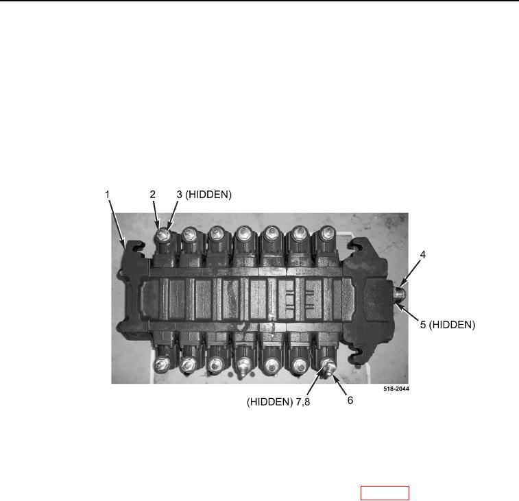
40. Remove 12 fittings (Figure 9, Item 2) and O-rings (Figure 9, Item 3) from backhoe control valve
(Figure 9, Item 1). Discard O-rings.
41. Loosen two nuts (Figure 9, Item 7) and remove elbow fittings (Figure 9, Item 6) and O-rings
(Figure 9, Item 8) from backhoe control valve (Figure 9, Item 1). Discard O-rings.
42. Remove fitting (Figure 9, Item 4) and O-ring (Figure 9, Item 5) from backhoe control valve (Figure 9, Item 1).
Discard O-ring.
Figure 9. Backhoe Control Valve Fittings.
0263
END OF TASK
CLEANING AND INSPECTION
0263
Clean and inspect all parts IAW Mechanical General Maintenance Instructions (WP 0369).
END OF TASK
INSTALLATION
0263
1. Install new O-ring (Figure 9, Item 5) and fitting (Figure 9, Item 4) on backhoe control valve (Figure 9, Item 11).
2. Install two new O-rings (Figure 9, Item 8) and elbow fittings (Figure 9, Item 6), and tighten nuts (Figure 9,
Item 7) on backhoe control valve (Figure 9, Item 1).
3. Install 12 new O-rings (Figure 9, Item 3) and fittings (Figure 9, Item 2) on backhoe control valve
(Figure 9, Item 1).