
TM 5-2420-231-23-3
0266
ASSEMBLY CONTINUED
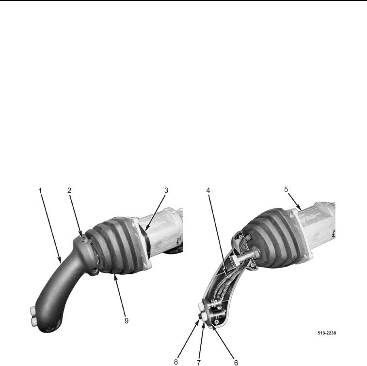
6. Route two AUX control switches (Figure 7, Item 7) and horn switch (Figure 7, Item 8) through joystick boot
(Figure 7, Item 9).
NOTE
Install AUX control and horn switches in position and orientation noted during removal.
7. Install two AUX control switches (Figure 7, Item 7) and horn switch (Figure 7, Item 8) on bezel
(Figure 7, Item 6).
8. Install two grip handle halves (Figure 7, Item 1) on joystick control valve (Figure 7, Item 5).
9. Install three screws (Figure 7, Item 2) on grip handle (Figure 7, Item 1).
NOTE
Install tiedown straps in location and quantity noted during removal.
10. Install new tiedown straps (Figure 7, Item 3) on AUX control switches wiring harness (Figure 7, Item 4).
Figure 7. Grip Handle.
0266