• Home
  • Download PDF
  • Order CD-ROM
  • Order in Print
Figure 20. Manual Control Lever and Handle Assembly.
Figure 23. Connector.

Tractor, Wheeled, Industrial Backhoe Loader Nsn 2420-01-532-3399
Page Navigation
  397    398    399    400    401  402  403    404    405    406    407  
img
.
TM 5-2420-231-23-3
0277
ASSEMBLY CONTINUED
NOTE
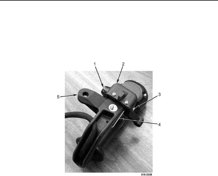
Install clam lock spring in position and orientation noted at removal.
11. Install clam lock spring (Figure 21, Item 4), clam lock lever (Figure 21, Item 2), and pin (Figure 21, Item 3) on
manual control lever (Figure 21, Item 5).
12. Install new push nut (Figure 21, Item 1) on pin (Figure 21, Item 3).
Figure 21. Clam Lock Lever.
0277
0277-15


Privacy Statement
Press Release
Contact

© Copyright Integrated Publishing, Inc.. All Rights Reserved.