
TM 5-2420-231-23-3
0277
ASSEMBLY CONTINUED
NOTE
Only perform steps 8 and 9 if replacing the manual control handle and manual control
lever. If reusing existing parts, proceed to step 11.
Prior to epoxying components, determine the proper position and orientation of manual
control handle in relation to the manual control lever to ensure proper operation of the
machine.
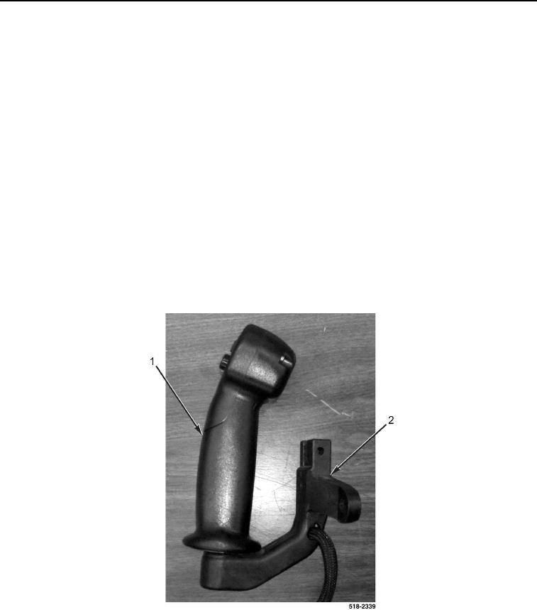
8. Apply sealing compound to new manual control handle (Figure 20, Item 1) and new manual control lever
(Figure 20, Item 2).
9. Apply loctite 326 epoxy to new manual control handle (Figure 20, Item 1) and new manual control lever
(Figure 20, Item 2).
CAUTION
The epoxy will set within 4 minutes, but takes 24 hours to cure at room temperature. Do
not handle manual control lever until epoxy has cured.
10. Install manual control handle (Figure 20, Item 1) on manual control lever (Figure 20, Item 2) and hold in posi-
tion for 4 minutes.
Figure 20. Manual Control Lever and Handle Assembly.
0277