
TM 5-2420-231-23-3
0277
ASSEMBLY CONTINUED
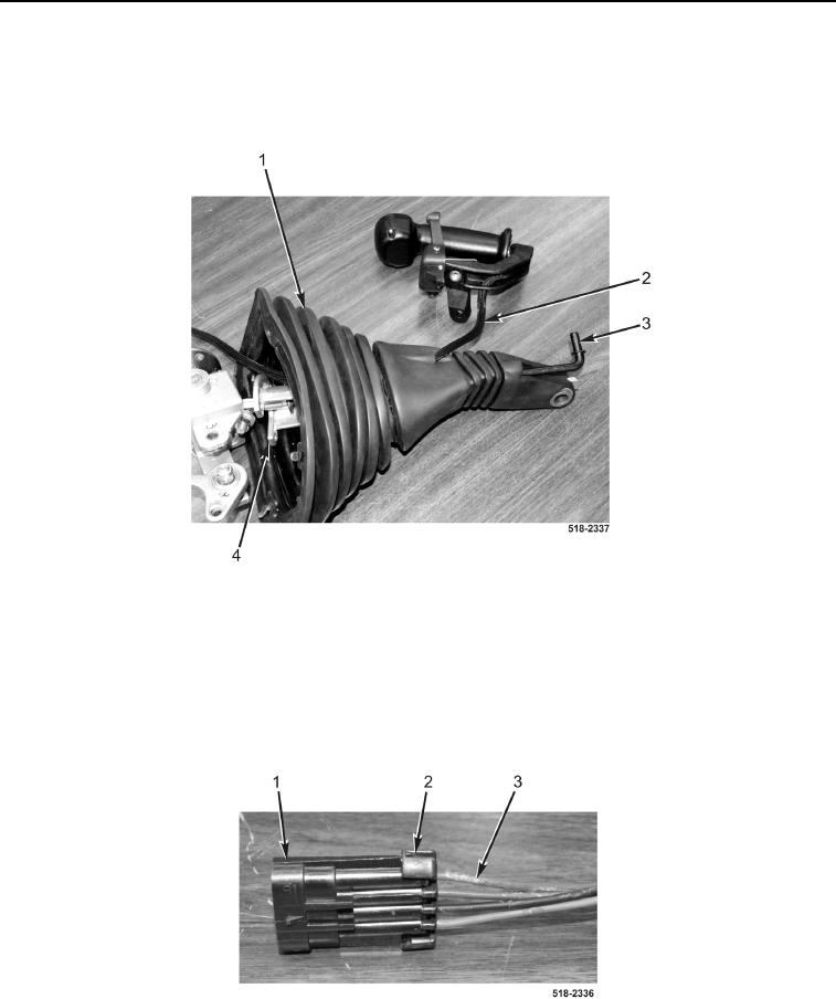
13. Install boot (Figure 22, Item 1) on manual control bracket (Figure 22, Item 4).
14. Install manual control lever assembly wiring harness (Figure 22, Item 2) on boot (Figure 22, Item 1).
15. Install pushrod (Figure 22, Item 3) on boot (Figure 22, Item 1).
Figure 22. Boot.
0277
NOTE
Install pins in connector cavities noted during removal.
16. Install four pins (Figure 23, Item 3) on connector (Figure 23, Item 1).
17. Install locking tab (Figure 23, Item 2) on connector (Figure 23, Item 1).
Figure 23. Connector.
0277