Home
Download PDF
Order CD-ROM
Order in Print
Figure 18. Bearings.
Figure 20. Manual Control Lever and Handle Assembly.
Tractor, Wheeled, Industrial Backhoe Loader Nsn 2420-01-532-3399
Page Navigation
395
396
397
398
399
400
401
402
403
404
405
TM
5-2420-231-23-3
0277
ASSEMBLY
CONTINUED
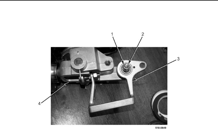
7.
Install
bellcrank
bracket
(Figure
19,
Item
3),
bolt
(Figure
19,
Item
2),
and
new
locknut
(Figure
19,
Item
1) on
bellcrank
joint
(Figure
19,
Item
4).
Figure
19.
Bellcrank Bracket.
0277
0277-13