
TM 5-2420-231-23-3
0277
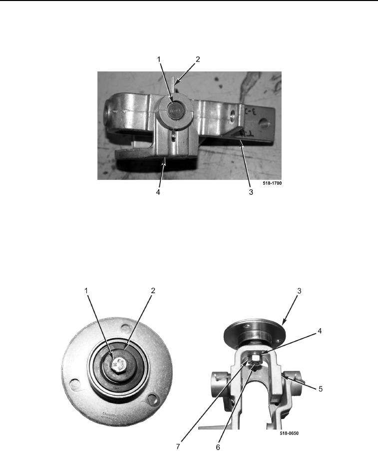
ASSEMBLY CONTINUED
5. Install two pins (Figure 17, Item 1) and new cotter pins (Figure 17, Item 2) on support bracket (Figure 17,
Item 4) and bellcrank joint (Figure 17, Item 3).
Figure 17. Pins.
0277
NOTE
Ensure bearing bolt holes are aligned during installation.
6. Install stud (Figure 18, Item 6), washer (Figure 18, Item 4), nut (Figure 18, Item 7), two bearings (Figure 18,
Item 3), washer (Figure 18, Item 2), and bolt (Figure 18, Item 1) on bellcrank joint (Figure 18, Item 5).
Figure 18. Bearings.
0277