
TM 5-2420-231-23-3
0277
ASSEMBLY CONTINUED
NOTE
Install rod bushing as noted at removal.
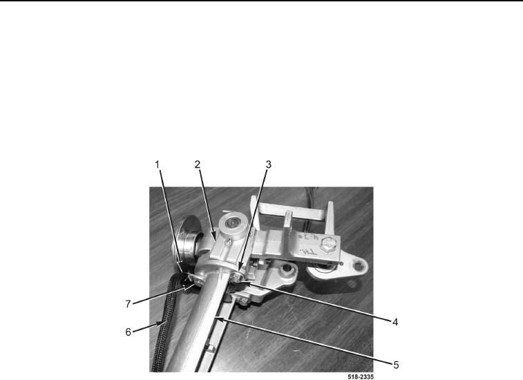
18. Install manual control bracket (Figure 24, Item 5), wiring harness (Figure 24, Item 6), clip (Figure 24, Item 1),
and bolt (Figure 24, Item 7) on linkage bracket (Figure 24, Item 2).
19. Install two washers (Figure 24, Item 3) and bolts (Figure 24, Item 4) on manual control bracket
(Figure 24, Item 5).
Figure 24. Linkage Bracket.
0277