
TM 5-2420-231-23-3
0297
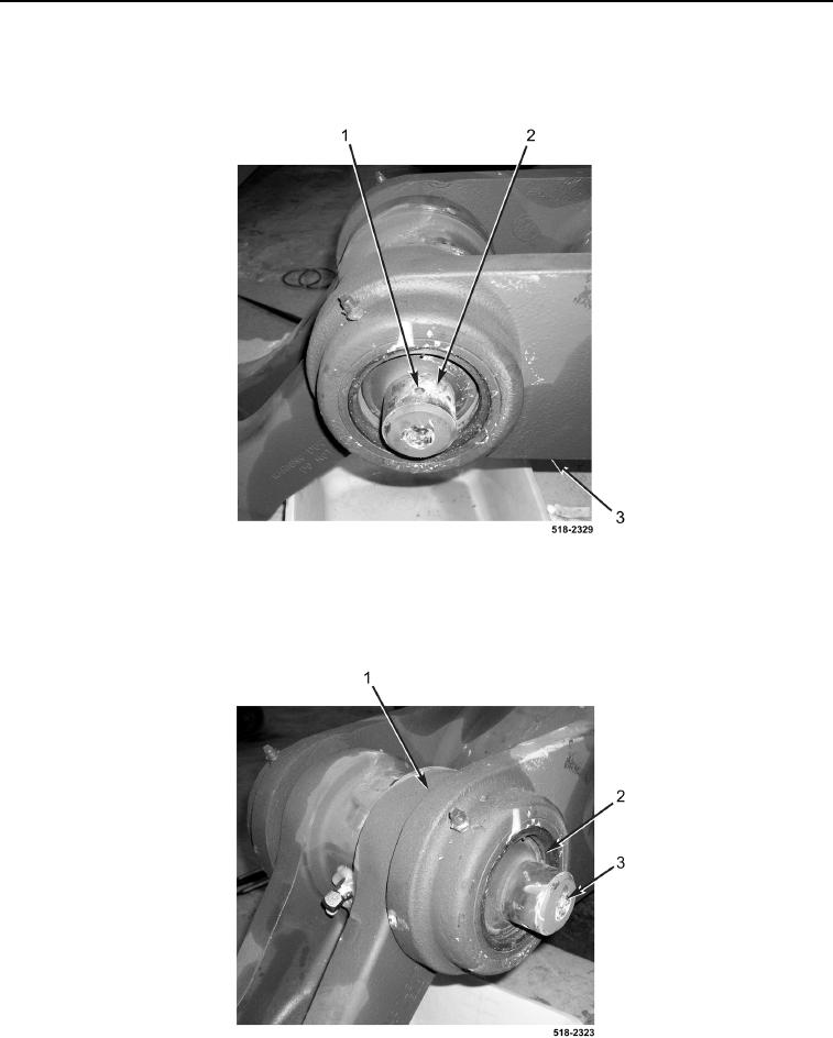
INSTALLATION CONTINUED
16. Install two coupler pins (Figure 19, Item 2) on backhoe dipper support arm (Figure 19, Item 3).
17. Install two new groove pins (Figure 19, Item 1) on coupler pins (Figure 19, Item 2).
Figure 19. Groove Pin.
0297
18. Push coupler pins (Figure 20, Item 3) inward.
19. Install locking ring (Figure 20, Item 2) on backhoe dipper support arm (Figure 20, Item 1).
Figure 20. Coupler Pin Locking Ring.
0297