
TM 5-2420-231-23-3
0297
INSTALLATION CONTINUED
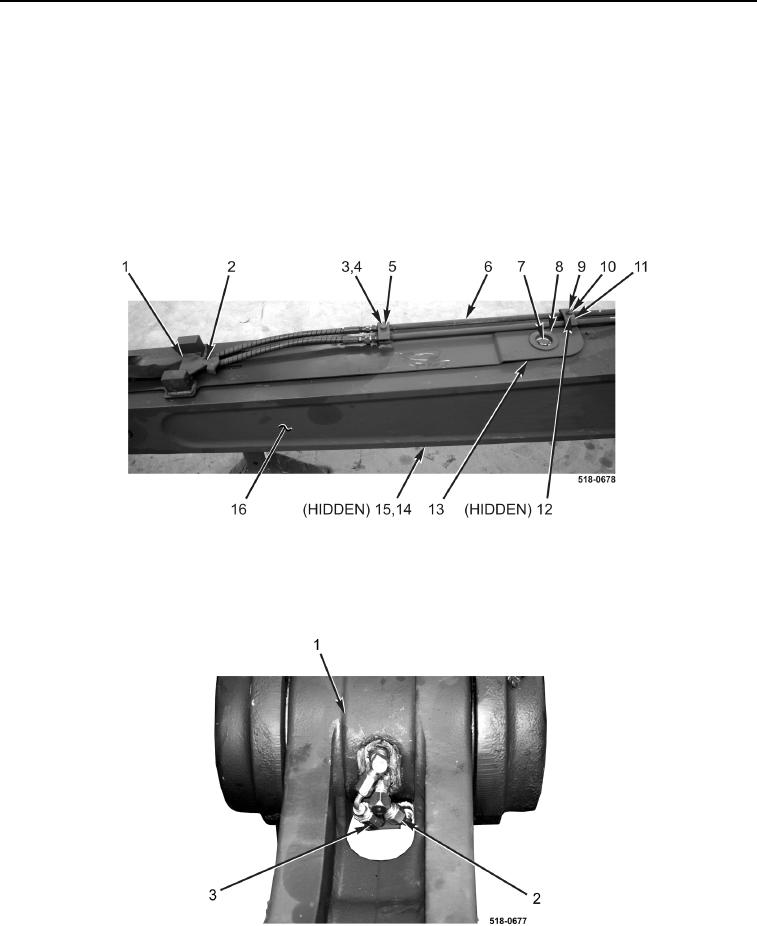
20. Install mounting plate (Figure 21, Item 13) convex washer (Figure 21, Item 8), bolt (Figure 21, Item 7), convex
washer (Figure 21, Item 15), and nut (Figure 21, Item 14) on backhoe dipper support arm (Figure 21, Item 16).
21. Position hydraulic tube assembly (Figure 21, Item 6) on backhoe dipper support arm (Figure 21, Item 16).
22. Install bracket (Figure 21, Item 2) and two capscrews (Figure 21, Item 1) on mounting plate
(Figure 21, Item 13).
23. Install clamp (Figure 21, Item 5), washer (Figure 21, Item 4) and bolt (Figure 21, Item 3) on mounting plate
(Figure 21, Item 13).
24. Install spacer (Figure 21, Item 12), clamp (Figure 21, Item 11), washer (Figure 21, Item 10), and nut (Figure 21,
Item 9) on mounting plate (Figure 21, Item 13).
Figure 21. Hydraulic Line Assembly.
0297
25. Connect hydraulic hose (Figure 22, Item 3) to backhoe dipper support arm (Figure 22, Item 1).
26. Connect hydraulic hose (Figure 22, Item 2) to backhoe dipper support arm (Figure 22, Item 1).
Figure 22. Hydraulic Lines.
0297