
TM 5-3805-255-14
0018
Table 1. Field PMCS for the H100C Loader - (Continued).
LOCATION
ITEM TO
CHECK/
NOT FULLY MISSION
CAPABLE IF:
SERVICE
ITEM NO. INTERVAL
PROCEDURE
Annually
Engine Valve
23
Clearance
(Cont.)
Adjustments
WARNING
Before making any adjustments place the battery disconnect
switch in the OFF position. Failure to comply could cause injury
to personnel and damage to equipment.
NOTE
Following this simplified procedure, all valves can be adjusted
quickly and accurately. Note that the engine need not be
cranked six times to position the piston of each cylinder on
TDC. All valves are adjusted by cranking the engine only twice.
Valve lash is adjusted with engine cold.
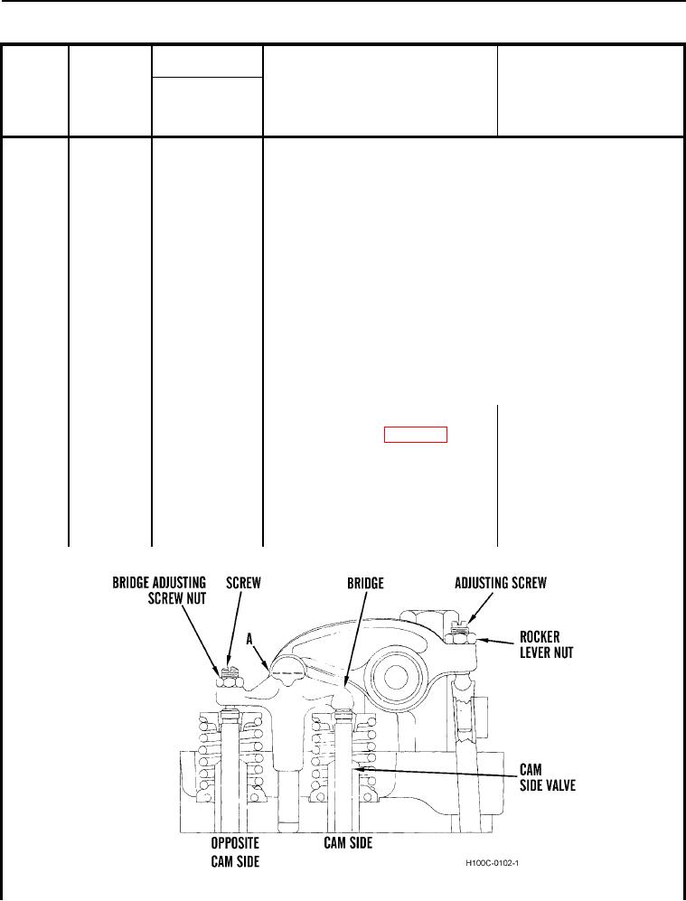
a. Remove cover and gasket from
both cylinder heads (WP 0027). Turn
crankshaft until number one piston is
on compression stroke and timing
pointer on front cover is in line with
TDC mark on vibration damper. Refer
to Figure 17 for numbering sequence
of valves.
Figure 18. Sectional View of Valve Mechanism.
0018
0018-31