
TM 5-3805-255-14
0090
INSTALLATION CONTINUED
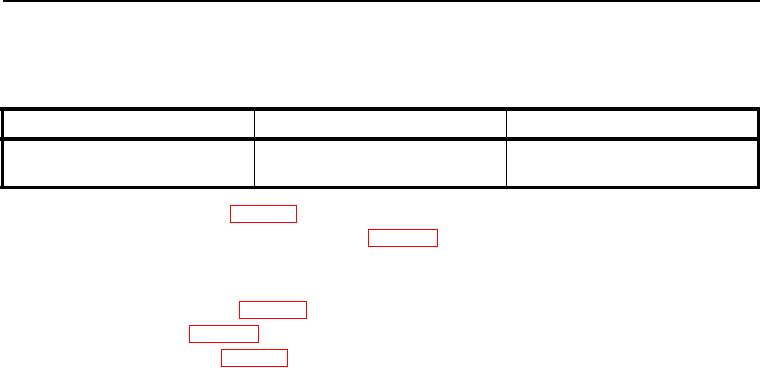
Table 2. Oil Seal and Wear Sleeve Dimension Chart.
Seal and Sleeve Location
Dimension A Sleeve Installed
Dimension B Seal Installed
090
090
090
Single or double Lip In Housing or
0.486 in.
0.680 in.
Retainer on Crankshaft
(12.34 mm)
(17.27 mm)
10. Install flywheel on crankshaft (WP 0091).
11. If removed, install crankcase front cover assembly (WP 0097).
12. Install piston cooling jets on right side of crankcase.
13. Install oil suction pipe and oil pan on engine.
14. Install cylinder head on engine (WP 0089).
15. Install engine on loader (WP 0022).
16. Check and fill all fluid levels (WP 0018).
17. Start engine and check for leaks.
END OF TASK
END OF WORK PACKAGE
0090-17/(18 blank)