TM 5-3805-258-24-1
T E S T I N G
A N D
A D J U S T I N G
F U E L S Y S T E M
15. Turn the crankshaft in a clockwise direction
approximately 45 degrees and then turn the
crankshaft in a counterclockwise direction
to the top center mark that was made in Step
14. If needed, adjust the dial indicator as in
Step 10.
16. Turn the crankshaft in a clockwise direction
approximately 45 degrees.
17.
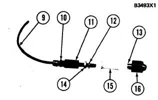
6 V 2 0 2 3 F L O W C H E C K I N G A D A P T E R G R O UP
9 . T u b e . 1 0 . C o n n e c t o r a s s e m b l y . 1 1 . F i t t i n g . 1 2 . S e a l-
ing washer. 13. Adapter. 14. Locknut. 15. Pin. 16. Nut.
18.
19.
Install 6V2023 Flow Checking Adapter Group
on No. 1 fuel injection pump. Use the proce-
dure that follows to install the group.
a.
b.
c.
d.
e.
f.
Turn fitting (11) out of adapter (13) until
5.0 mm (.20 in.) of pin (15) can be seen.
Put 6V2023 Flow Checking Adapter Group
on No. 1 fuel injection pump and tighten
nut (16) to 40 N·m (30 lb. ft.).
Turn fitting (11) into adapter (13) until
pin (15) just makes contact with the reverse
flow check valve in the fuel injection pump
bonnet. This is the point of first resistance.
Turn the fitting into the adapter an addi-
tional 1/4 turn.
Move sealing washer (12) against the adap-
ter. Tighten locknut (14) finger tight against
sealing washer (12).
Tighten tube (9) to connector assembly
(10) so that the end of tube (9) is in a posi-
tion above horizontal and higher than the
end on the connector assembly.
Disconnect the fuel line at the fuel filter. Use
an adapter to connect 5J4634 Hose Assembly
(19) to the fuel filter base.
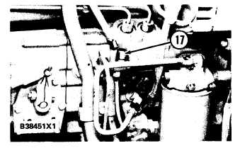
Disconnect the fuel return line from the con-
stant bleed valve. Put cap (17) on the constant
bleed valve.
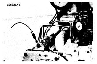
F L O W C H E C K I N G A D A P T E R G R O U P I N S T A L L E D
( T Y P I C A L
E X A M P L E)
C O N S T A N T B L E E D V A L VE
( T Y P I C A L E X A M P L E)
17. Cap.
20. Put 1 gal. (4 liters) of clean fuel in the tank
assembly. Move the governor lever to full
FUEL-ON position. Put 105 kPa (15 psi) of
air pressure in the tank. Use the hand pump
or shop air.
CAUTION
If shop air is used, make an adjustment to the
regulator so the air pressure in the tank is a
maximum of 105 kPa (15 psi).
21.
22.
23.
Put pan (18) under the end of tube (9) for the
fuel that comes out of the tube.
Turn the crankshaft, slow, in a counterclock-
wise direction. Do this until the flow of fuel
from the end of tube assembly (9) is 6 to 12
drops per minute.
Stop rotation of the crankshaft when the flow
of fuel is 6 to 12 drops per minute. Take a
reading of the measurement on dial indicator
(3).
4-15