TM 5-3805-258-24-1
H Y D R A U L I C
S Y S T E M
RELIEF VALVE TESTS
WARNING
Make reference to WARNING on first page of
HYDRAULIC SYSTEM TESTING AND ADJUST-
ING section.
Tools Needed:
6V4161 Hydraulic Test Group
5S5123 Hydraulic Test Group
8S3033 Electric Hydraulic Pump
5H4019 Cover
8J6559 Plug
1. Lower the bucket so it is on the ground and can
not be tilted. Remove the cover, over control
valve, from the front of the loader frame.
2. Get the temperature of the oil up to normal
operating temperature.
Main Relief Valve
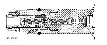
L I F T A N D T I L T C O N T R O L V A L VE
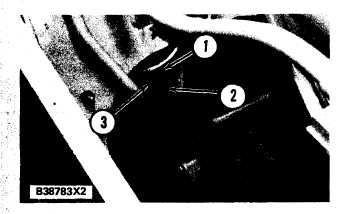
1. Plug (in relief valve). 2. Main relief valve. 3. Plug (in
Tee Test plug).
1. Install P1414 Connector where plug (3) was
removed. Install a pressure gauge (0 to 28000
kPa (0 to 4000) psi) and hose on the connector.
Alternate Step 1. Remove plug (3) and permanent-
ly install a 6V3965 Valved Nipple where plug (3)
was removed. Connect a hose to the nipple with a
6V4143 Coupler. Install the pressure Gauge.
2. Start the engine and raise the lift arms to the
top of their travel.
3.
T E S T I N G
A N D
A D J U S T I N G
Increase the engine speed to high idle rpm. Look
at the test gauge and move the control lever to
the RAISE position. The high reading on the
gauge is the pressure setting of the main relief
valve (do not keep the control lever in RAISE
position, at the relief valve setting, more than 5
seconds). The correct pressure setting of the
main relief valve is 19 000 + 500 - 200 kPa (2750
+ 72 - 29 psi).
M A I N R E L I E F V A L VE
1. Plug. 4. Plunger.
4. If a pressure setting change is needed, lower
the bucket to the ground and stop the engine.
Remove plug (1) from the main relief valve.
Turn plunger (4) clockwise for an increase or
counterclosewise for a decrease in the pres-
sure setting of main relief valve (2).
5. When the pressure setting of main relief valve
(2) is correct, install plug (1), remove the hose
with the pressure gauge, install plug (3) and
the cover over the control valve.
NOTE: If other tests are to be made, do not install
the cover.
Relief Valve For Rod End Of Tilt Cylinder
1. Stop the engine. Loosen, but do not remove
plug (1) to release the pressure of the oil at the
rod end of the tilt cylinder.
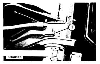
L E F T S I D E O F T I L T C Y L I N D ER
1. Plug in rod end circuit.
4-76