ENGINE
TM 5-3805-258-24-2
DISASSEMBLY AND ASSEMBLY
CYLINDER HEAD
DISASSEMBLE CYLINDER HEAD
Tools Needed
A
B
C
D
E
6V3129 Nozzle Puller Group 1
5S1330 Valve Spring
Compressor
1
8S2263 Valve Spring Tester
1
7S8859 Guide Driver
1
9S3080 Valve Seat
Insert Group
1
1.
2.
3.
4.
5.
6.
7.
start by:
a) remove cylinder head
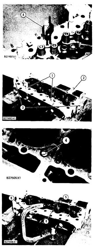
Use tooling (A) to remove the fuel injection
nozzles from the cylinder head.
Remove brackets (1) for the fuel injection line
clamps.
Remove water temperature sending unit (2).
Remove lifting brackets (3).
Remove and install water directors (4) as fol-
lows:
a)
b)
c)
Remove old water directors (4) from the
cylinder head.
Clean the cylinder head.
Install new water directors in the cylinder
head with the notch in the water director in
alignment with the “V” mark on the cylin-
der head. Install the water directors to a
depth of 0.8 ± 0.6 mm (.031 ± .023 in.)
below the surface of the cylinder head.
Use tooling (B) to put valve spring (6) in
compression. Remove locks (5) from the valve
stem. Carefully remove tooling (B), rotocoil,
spring and valve. Put identification on the
valves with respect to their location in the cylin-
der head. Remove the remainder of the valves
the same way.
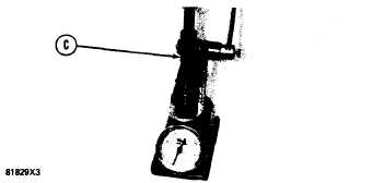
Use tooling (C) to check the valve springs. The
spring force is 257 ± 25 N (57.6 ± 5.6 lb.).
The length of the spring under test force is
44.86 mm ( 1.766 in.). The free length after test
is 52.1 mm (2.05 in.). Check all the valve
springs.
5-127