TM 5-3805-258-24-2
ENGINE
CYLINDER HEAD
DISASSEMBLY AND ASSEMBLY
8.
9.
10.
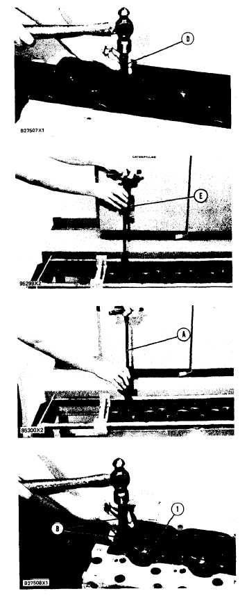
Use tooling (D) to remove the valve guides
from the cylinder head.
Use tooling (E) to remove the valve seat inserts
from the cylinder head.
Clean and remove any rough places (burrs)
from the valve seat bores.
NOTE: For reconditioning information of the cylin-
der head see SERVICE TRAINING MEETING
GUIDE Form JEG02327.
ASSEMBLE CYLINDER HEAD
1100-16
Tools
Needed
A
B
C
D
E
9S3080 Valve Seat
Insert Group
1
7S8859 Guide Driver
1
7S8858
Bushing
1
5S1330 Valve Spring
Compressor
1
5S1322
Lock
Inserter
1
8S2252 Carbon Seal Tool*
1
*The 8S2252 Carbon Seal Tool must have a modifi-
cation made to it before it can be used with the
8N7002 Fuel Injection Nozzle. Special Instruction
Form No. SEHS7292 has the information needed to
make the modification to the tool.
1.
2.
3.
Lower the temperature of (freeze) the new
valve seat inserts, Use tooling (A) to install the
new valve seat inserts. Do not increase the dia-
meter of the extractor in the valve seat insert
when the insert is installed in the cylinder head.
Put clean oil on the outside diameter of the
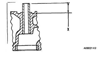
valve guides. Use tooling (B) to install valve
guides (1) in the cylinder head. Tooling (B) will
install the valve guides so dimension “X” will
be correct. Dimension “X” must be 22.23 ±
0.25 mm (.875 ± .010 in.). The minimum in-
side diameter of the valve guides after installa-
tion must be 9.456 mm (.3723 in.). Clean the
valve guides after installation.
Grind the valve seat inserts according to speci-
fications given in SPECIFICATIONS section.
5-128