ENGINE
TM 5-3805-258-24-2
DISASSEMBLY AND ASSEMBLY
PISTONS
DISASSEMBLE PISTONS
1214-15
Tools Needed
A
B
Ring Expander
1
5F3639
Press Group
1
8F24
Hose Assembly
1
1P2375
Coupler Assembly
1
1P2376
Coupler Assembly
1
5F8719
Hand Pump (or electric)
1
6V2050
Tool Group
1
1.
2.
3.
4.
5.
6.
7.
8.
9.
start by:
a) remove pistons
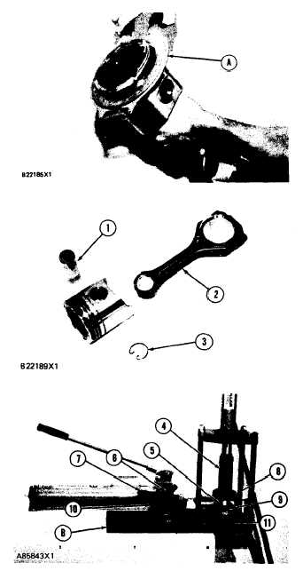
Remove the rings from the piston with tool (A).
Remove the bearings from the connecting rod
and connecting rod cap.
Remove retaining rings (3), pin (1) and con-
necting rod (2) from the piston.
See USE OF PISTON PIN BEARING RE-
MOVAL AND INSTALLATION TOOLS,
SPECIAL INSTRUCTIONS, Form No.
SMHS7295-02 for more information of re-
moval and installation of piston pin bearings.
Heat the connecting rod to a temperature of
176 to 260°C (350 to 500°F). Put 6V3029
Spacer (11) in the base plate. Put the connect-
ing rod on the base plate of tooling (B).
Put the connecting rod piston pin bearing end in
the center of the port assembly of tooling (B).
Install pin (6) in the center of the bore for the
connecting rod bearings.
Install 6V2049 Adapter (9). Put the hole in the
adapter in alignment with the hole in the base
plate of tooling (B).
Install clamp bar (10) and clamp pin (7).
Install new piston pin bearing (5) on adapter
(9).
NOTE: The old bearing is pushed out by tooling (B)
as the new bearing is installed.
10.
11.
12.
13.
14.
Put 5P8645 Adapter (8) in position as shown
with the taper side down. The piston pin bear-
ing joint must be in alignment with the hole in
adapter (9) and the base plate of tooling (B).
Put pusher (4) on adapter (8).
Use tooling (B) to push the new piston pin
bearing into the connecting rod until adapter
(8) of tooling (B) makes full contact with the
connecting rod surface.
Remove the connecting rod and the old piston
bearing from tooling (B).
Check the piston pin bearing bore diameter
after the bearing is installed. The correct di-
mension is 43.210 ± 0.008 mm (1.7012 ±
.0003 in.).
5-133