OPERATOR’S STATION
TM 5-3805-258-24-2
DISASSEMBLY AND ASSEMBLY
7.
8.
9.
10.
11.
12.
13.
14.
15.
HYDRAULIC CONTROL
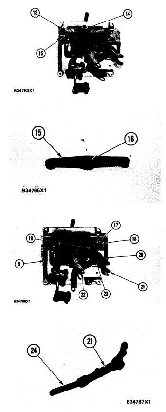
On models 950BNS and 950BS, loosen the
setscrew and remove collar (14) from the shaft.
Models 950BNSCE and 950BSCE do not use
collar.
Remove two bolts (13), the washers and re-
move bracket (15 ) from the panel.
Remove bearing (16) from bracket (15) by
hand.
Remove bolt and washer (18) and shaft assem-
bly (17) from panel (9).
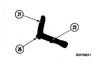
Remove washer (19), lever (20), spacer (23)
and bellcrank (21) from panel (9).
If necessary, remove the bolt and link (22) from
lever (20). Remove the locknut and roller from
lever (20).
Remove the cotter pin, washer and pin to re-
move link (24) from bellcrank (21).
Remove the locknut and roller (25) from bell-
crank (21).
Use tool group (A) and remove bearings (26)
from bellcrank (21) and lever (20).
5-523


