TM 5-3805-258-24-2
OPERATOR’S STATION
DISASSEMBLY AND ASSEMBLY
16.
17.
18.
19.
20,
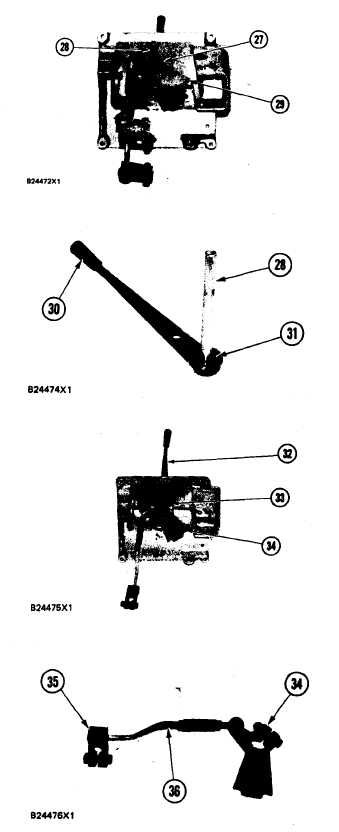
HYDRAULIC CONTROL
Loosen the locknut and bolt (27). Remove lever
(29) and the control rod from the shaft of lever
assembly (28).
Remove the key from the shaft of lever assem-
bly (28). Remove lever assembly (28) from the
panel.
Remove bearing (31), the nut and knob (30)
from lever assembly (28).
Loosen the locknut and bolt (33). Remove lever
(34) and the control rod from the shaft of lever
assembly (32).
Remove the two bolts and remove levers (34)
and (35) from control rods (36).
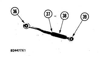
21. Loosen nuts (37) and remove rod end (39) and
the nut from rod (38). Remove rod (38) and nut
from rod (36).
22. Follow Steps 20 and 21 to disassemble the other
control rod and lever (29).
GROUP
5-524