OPERATOR’S STATION
TM 5-3805-258-24-2
DISASSEMBLY AND ASSEMBLY
23.
24.
25.
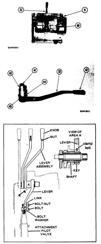
HYDRAULIC CONTROL GROUP
Use tool (B) and remove ring (40). Remove
the bearing from over the shaft of lever
assembly (32).
Remove lever assembly (32) from panel (9).
Remove key (43), bearing (44), two bearings
(41) and knob (42) from lever assembly (32).
26. Use tool (B) to remove ring (45) from lever
assembly (32).
NOTE: For the third attachment control lever in
the hydraulic control group:
26a.
26b.
26c.
26d.
Remove the bolts, nuts, washer
from the end of the lever.
and link
Loosen clamp bolt on lever. Remove the lever
and the key from the shaft of lever assembly.
Remove lever assembly from the panel (9).
Remove the knob and nut from the end of
the lever assembly.
5-525